Step-by-Step Guide
Complete guide to adding an inverter and setting up monitoring.
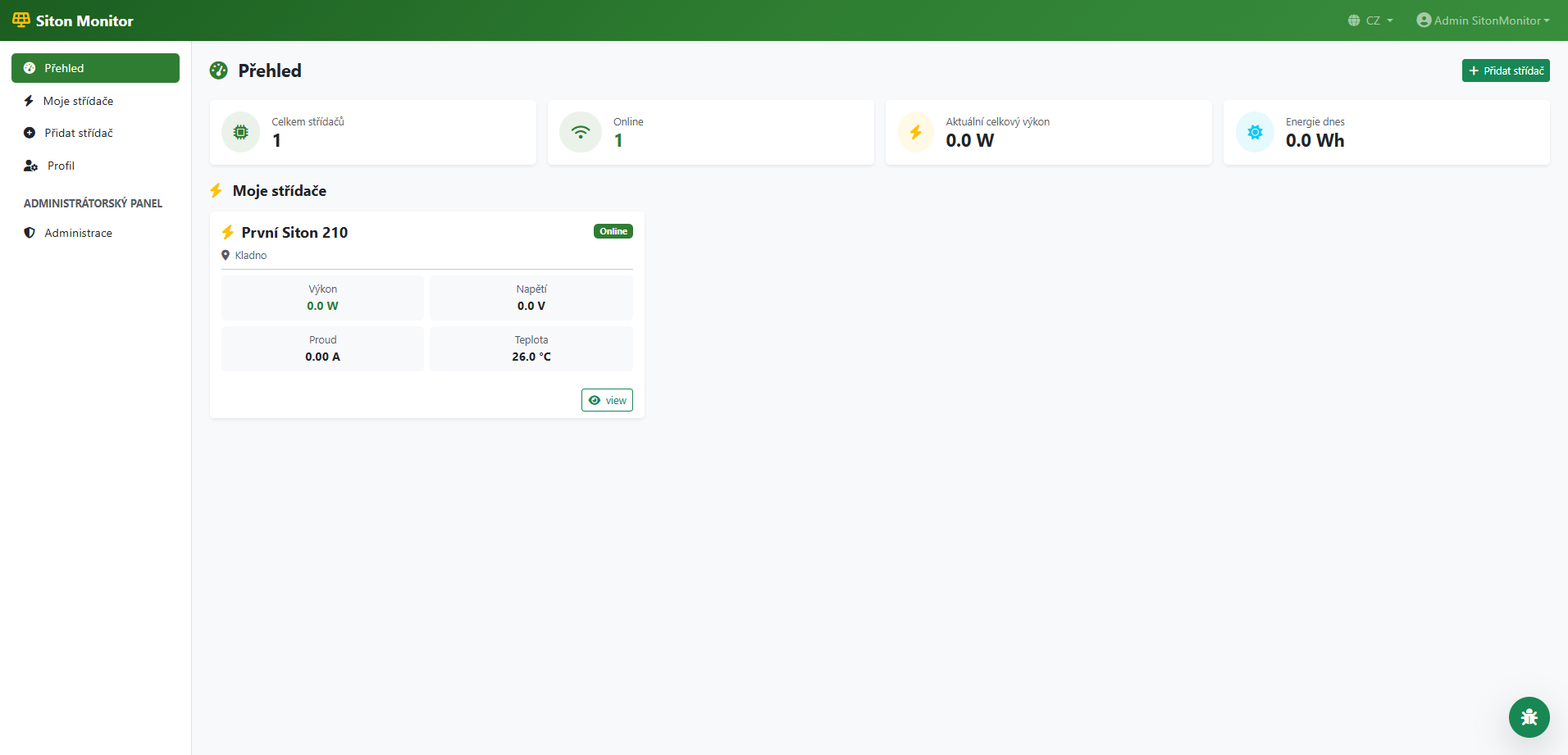
Go to Dashboard
After logging in, your Dashboard will appear. Click the green "+ Add Inverter" button in the top right corner.
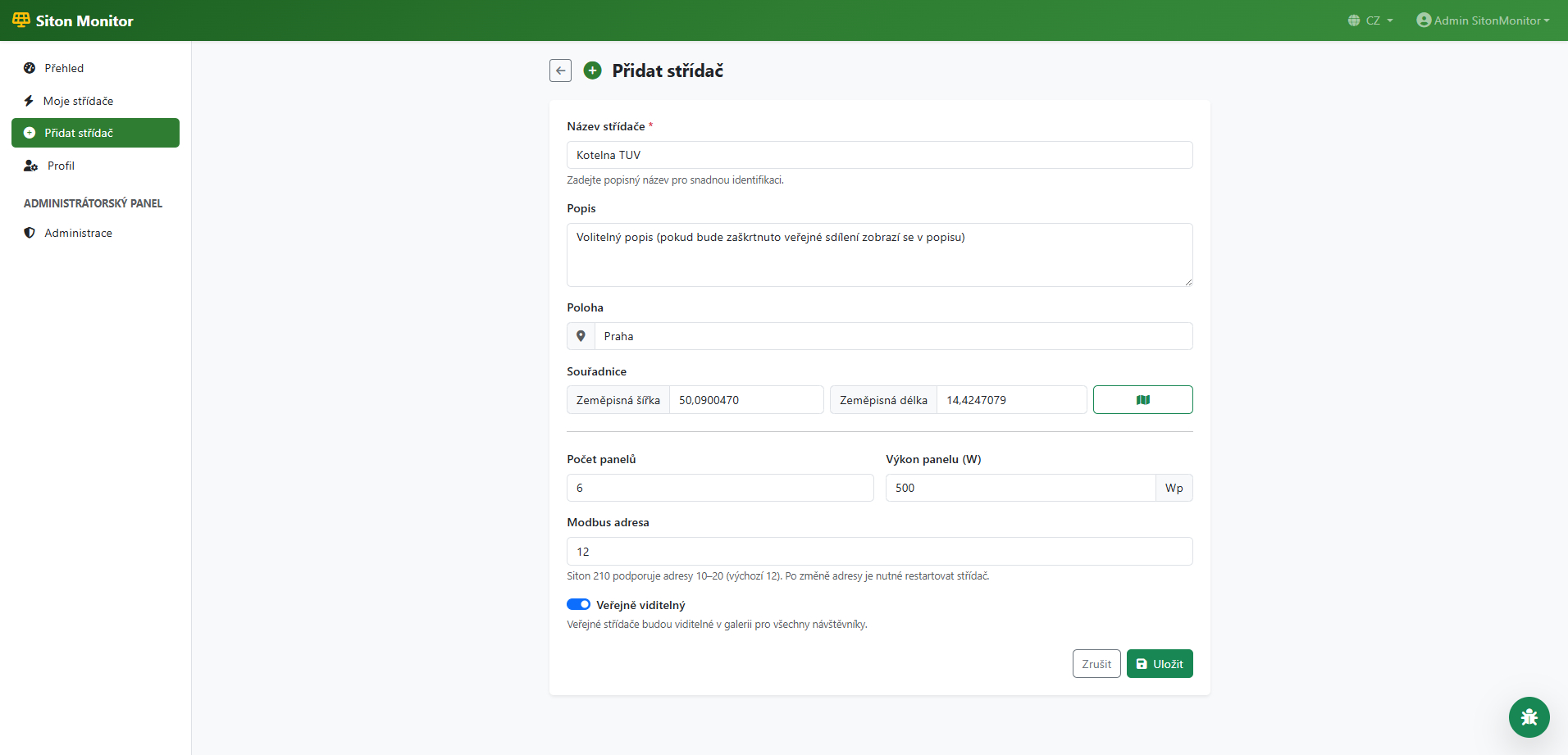
Fill in the Add Inverter Form
Enter the inverter name (e.g. "Boiler Room"), optional description, installation location, number and wattage of panels. Leave the Modbus address at default value 12 unless you changed it on the inverter.
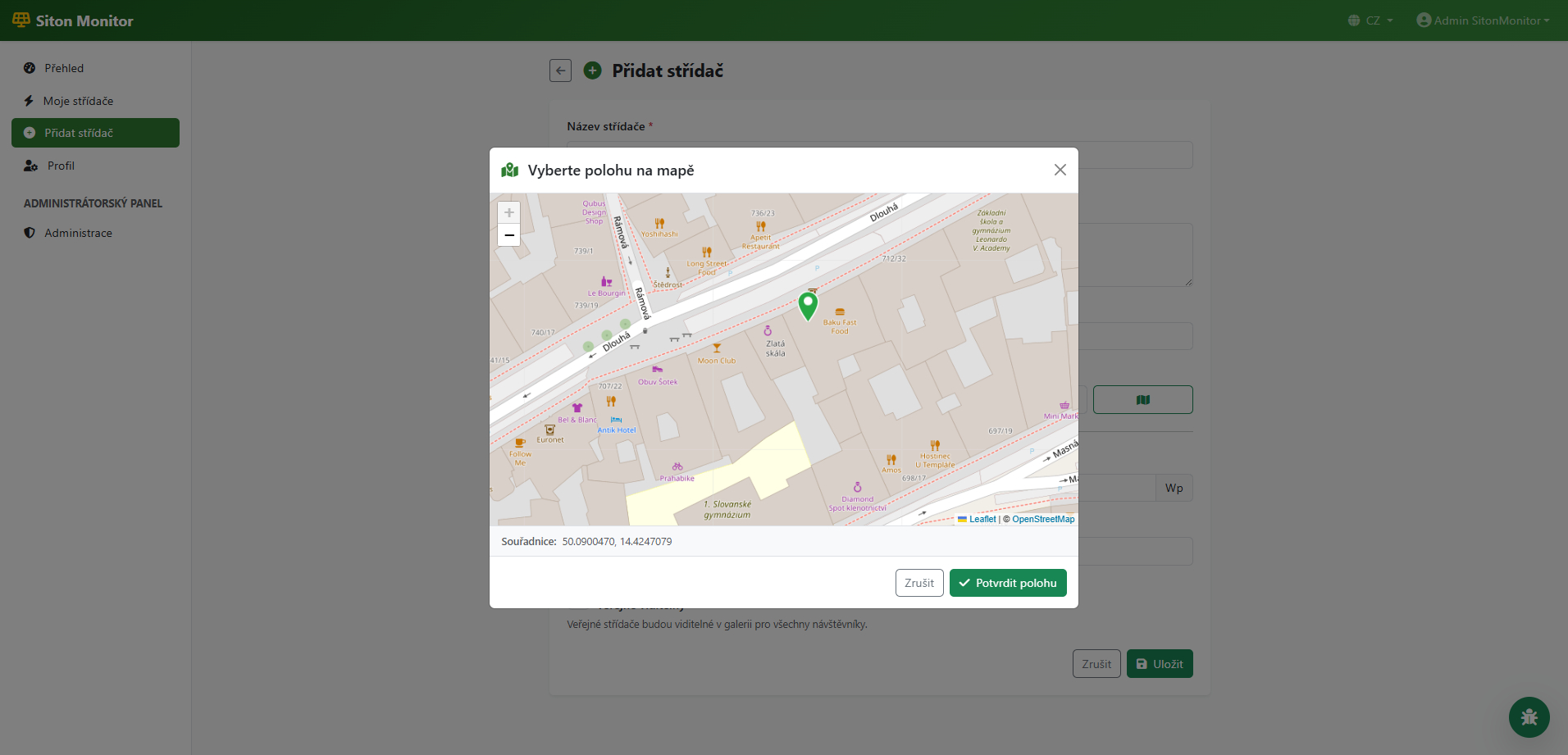
Select Location on Map (Optional)
Click the map icon button next to the coordinates. A map will open where you can click to select the exact location of your inverter. Confirm with the "Confirm Location" button.
Save Inverter
Click the "Save" button. After saving, you will be automatically redirected to the "Firmware Setup" page where you will find everything needed to configure the ESP.
Open the Firmware Page
In the dashboard, click on your inverter and then on the "Firmware" tab. On the page you will find the "Quick Install from Browser" section with the "Upload Firmware" button.
Connect ESP and Select Port
Connect the ESP to your computer via USB cable. Select the board variant (ESP8266 or ESP32) and click "Upload Firmware". The browser will show a dialog for selecting a serial port — choose your ESP COM port and click "Connect".

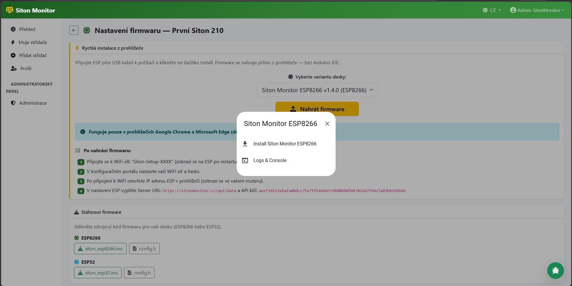
Confirm Installation
After connecting, a dialog will appear with "Install Siton Monitor" — click it to start the installation.
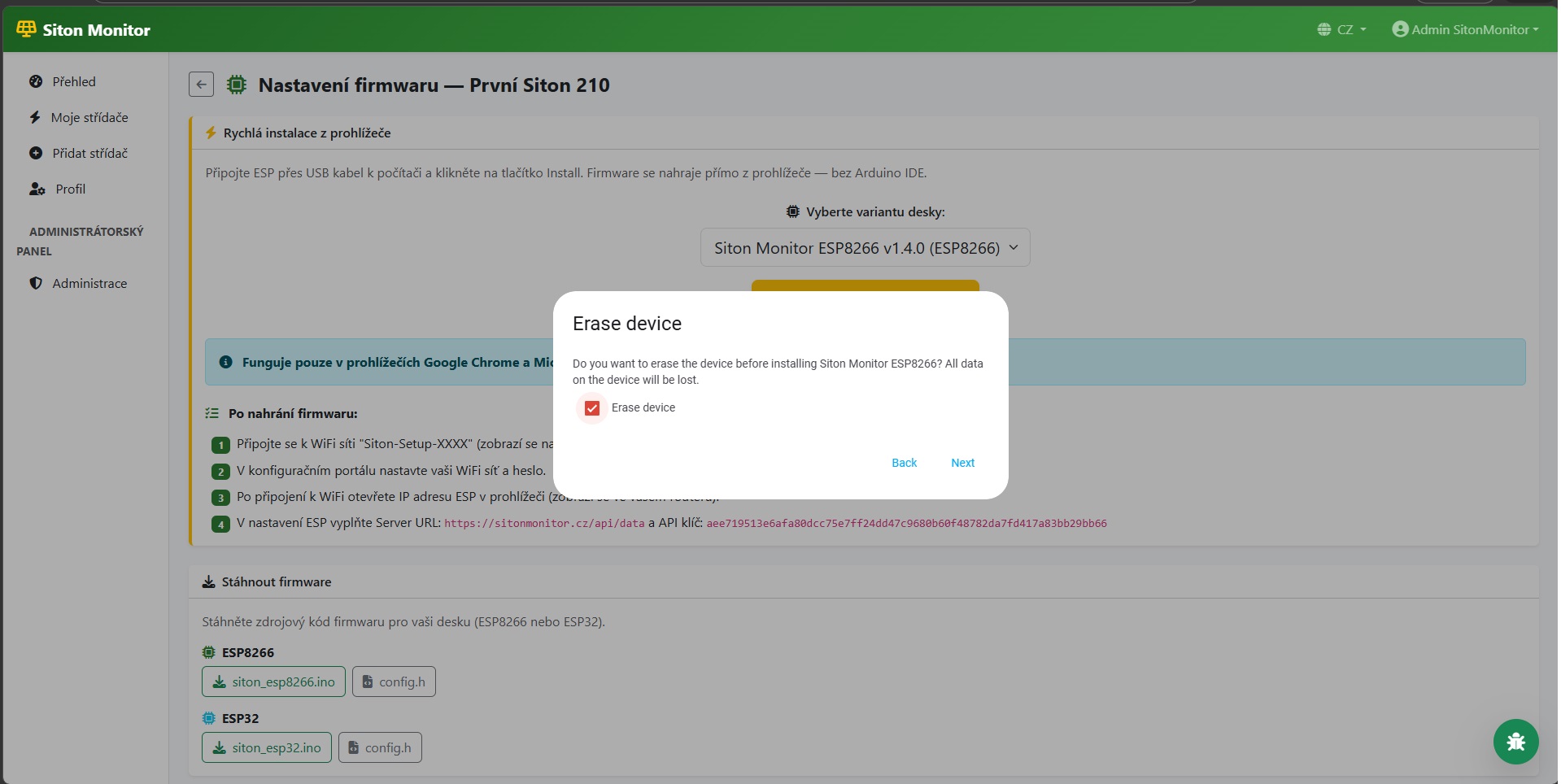
Erase ESP Before Upload
For the first upload, we recommend checking "Erase device" to clear old memory. Click "Next" to continue.
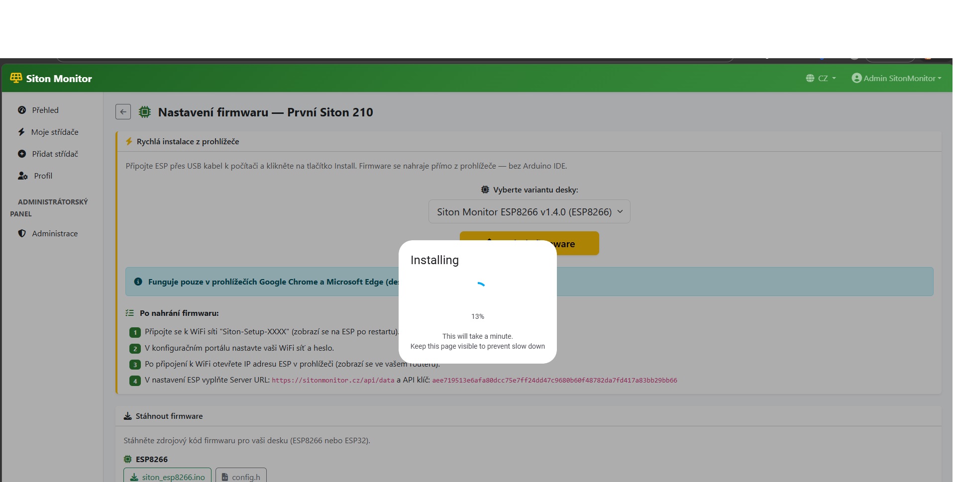
Wait for Completion
The firmware is being uploaded to the ESP. Progress is shown in percent. Do not disconnect the USB cable and keep the page open. The ESP will restart automatically when finished.
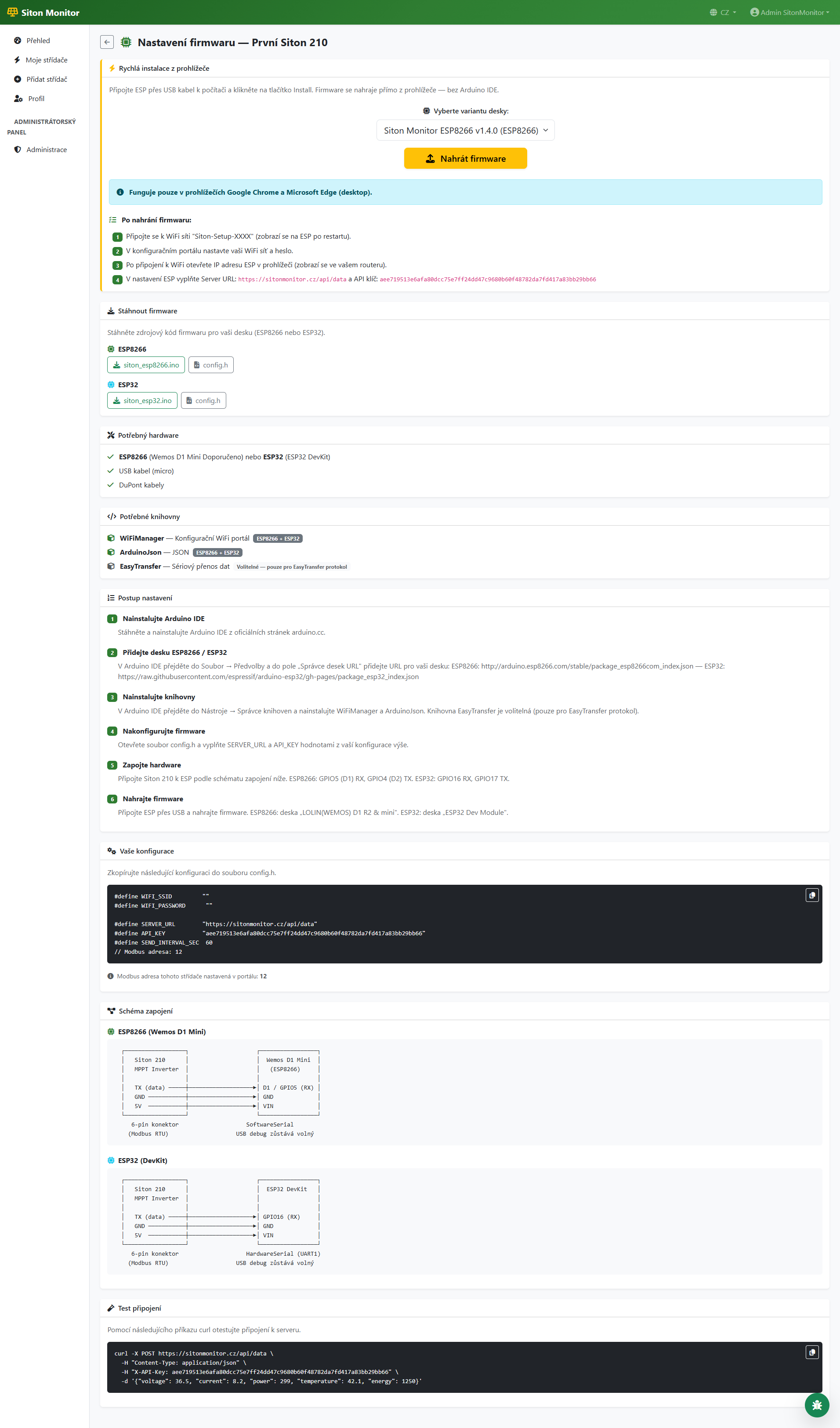
Firmware Page
The Firmware page contains everything you need: hardware list, required libraries, setup instructions, your configuration (SERVER_URL and API_KEY), wiring diagram, and download buttons for firmware files.
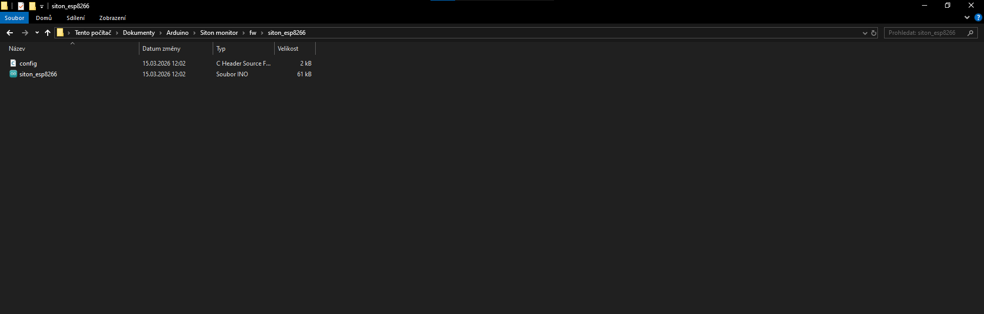
Download and Save Firmware Files
On the Firmware page, click the "siton_esp8266.ino" and "config.h" buttons to download both files. Save them in the same folder — the folder must be named "siton_esp8266" (Arduino IDE requires this).
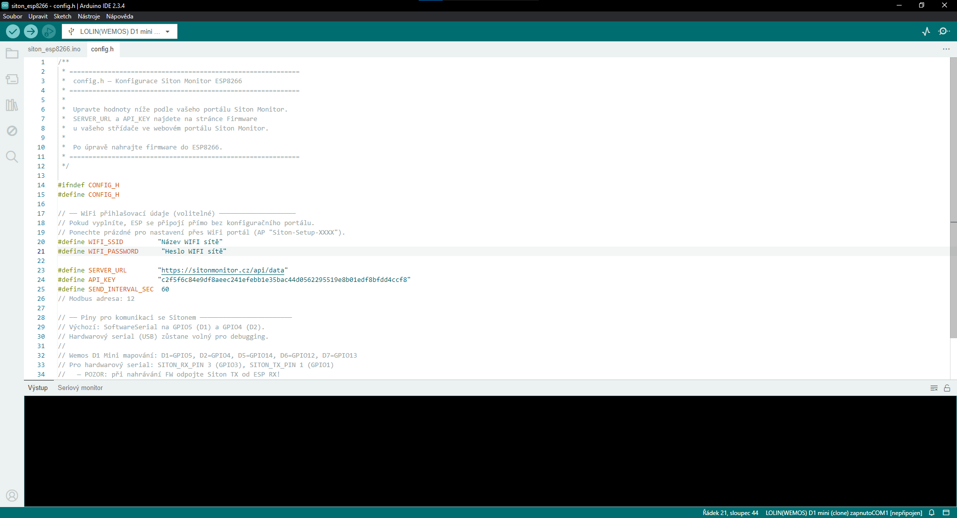
Edit Configuration in Arduino IDE
Open siton_esp8266.ino in Arduino IDE. Switch to the "config.h" tab and fill in the values from the portal: WIFI_SSID, WIFI_PASSWORD, SERVER_URL, and API_KEY. You can find these on the Firmware page of your inverter.
Upload Firmware to ESP
Connect the ESP to your computer via USB cable. In Arduino IDE, select the correct board and COM port. Click the "Upload" button (right arrow). Wait for the upload to complete.
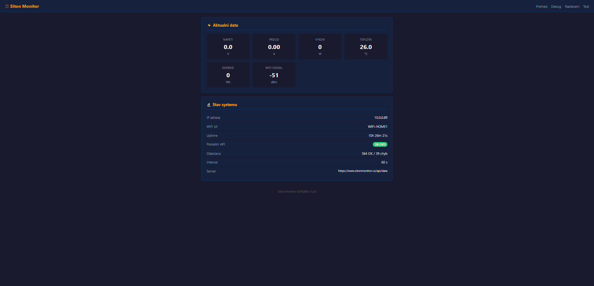
After uploading the firmware and connecting to your WiFi network, open the ESP IP address in your browser. The interface provides an overview, settings, and diagnostics.
Overview — Live Data
The main page shows current measured values (voltage, current, power, temperature, energy) and system status (IP address, WiFi network, uptime, API communication status, number of data points sent).
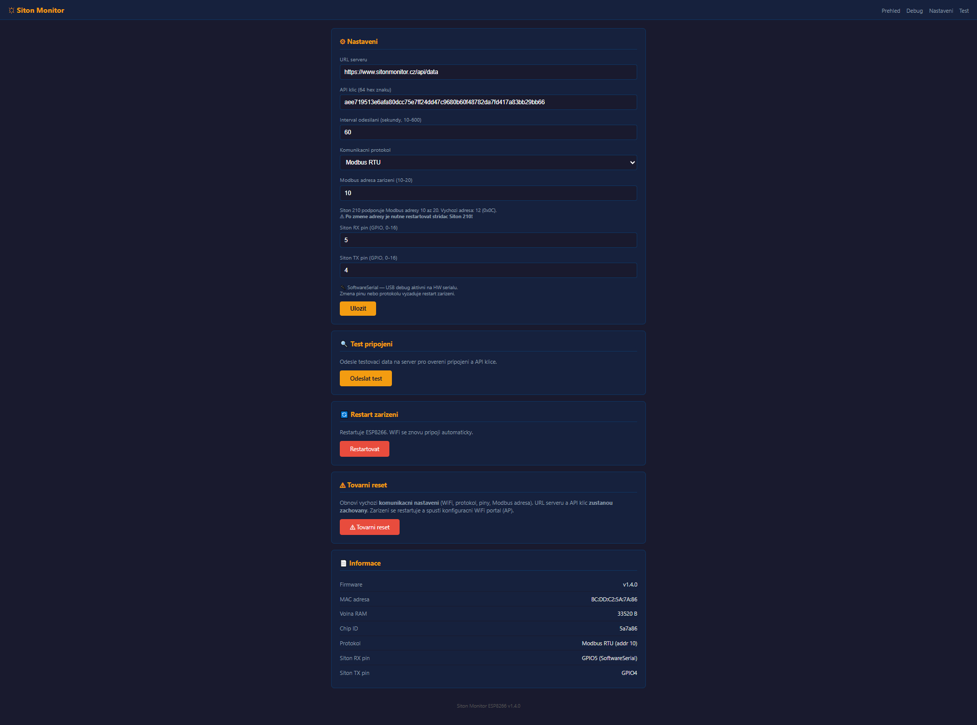
Settings
On the Settings page, you can change the server URL, API key, data sending interval, communication protocol (Modbus RTU), Modbus address, and communication pins directly in your browser. Changes are saved to ESP memory.
Debug — Communication Diagnostics
The Debug page is used to diagnose communication between the ESP and the Siton 210 inverter. When stopped, you can see the current communication settings and empty statistics.
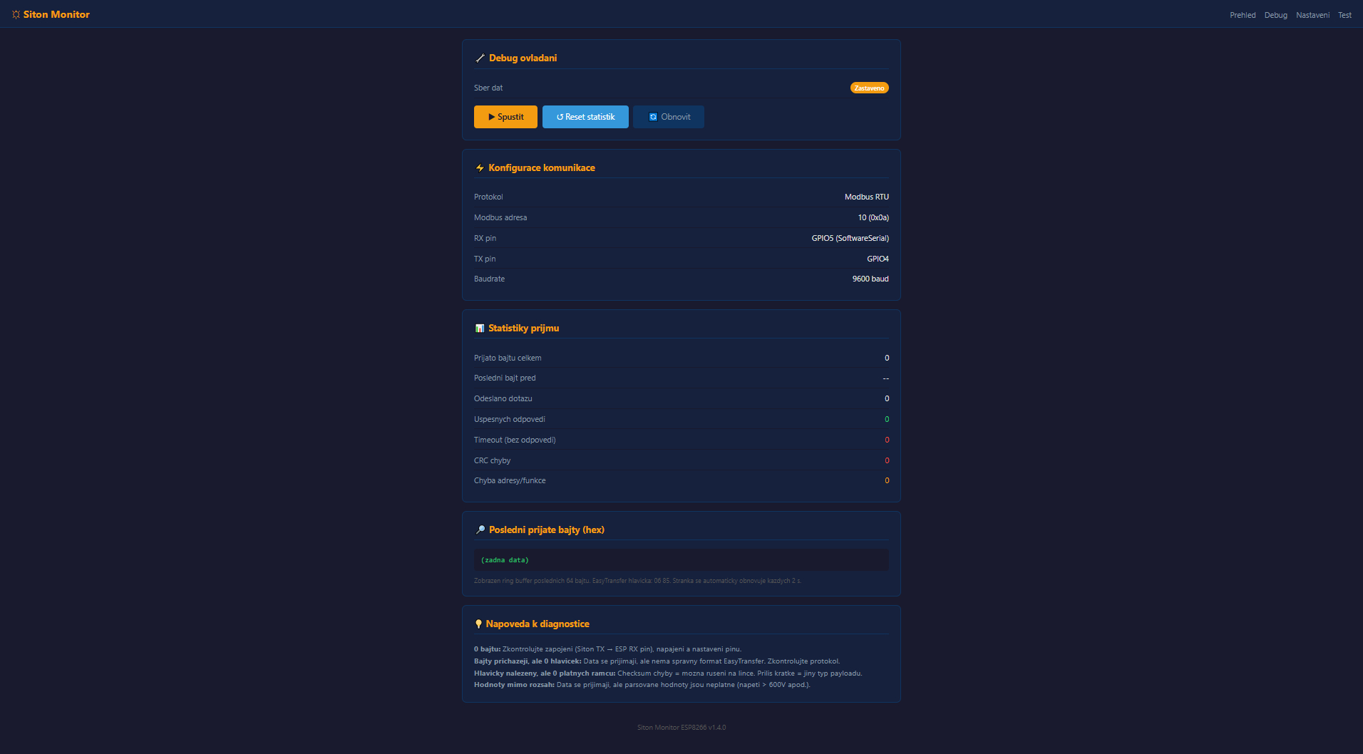
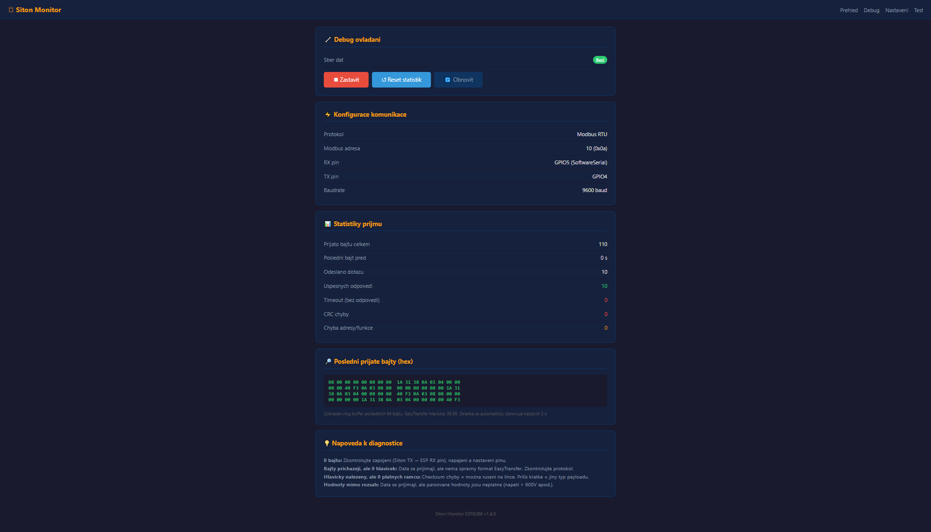
Debug — Data Collection Running
After clicking "Start", the ESP begins actively querying the inverter. Reception statistics are displayed: bytes received, successful responses, timeouts, and CRC errors. The last received bytes are shown in hex format for advanced diagnostics.
Done!
Your Siton 210 inverter is now connected to the Siton Monitor portal. Data will start appearing in the dashboard after the first successful transmission.
Register